
Félix L. Martínez Viviente, Juan Hinojosa Jiménez, Ginés Doménech Asensi, Alejandro Melcón Álvarez
Escuela Técnica Superior de Ingeniería de Telecomunicación (ETSIT)
Universidad Politécnica de Cartagena (UPCT)
I. INTRODUCTION
In recent years, a region of the electromagnetic spectrum that has so far been little known and studied has attracted a great deal of interest. This is the so-called THz region, a frequency range between the microwave region and the optical spectrum. This frequency range is also known as the THz-jump, because it effectively constitutes a jump between two regions of the electromagnetic spectrum in which very different techniques are used for the generation and manipulation of electromagnetic waves. On the one hand, towards lower frequencies, the techniques for microwave generation are of the electronic type, either in vacuum tubes by the ballistic motion of electrons controlled by electric or magnetic fields (e.g. in devices such as the magnetron or klystron), or by electron oscillation in solid state devices such as Gunn diodes, IMPATT, tunnel diodes, and certain types of field effect transistors. On the other hand, towards the higher frequency range, we enter the optical region of the spectrum (starting with the extensive infrared range), where the previous techniques are inefficient and the generation of light is carried out in a completely different way, in devices as disparate as lasers or different types of lamps, either thermal or gas discharge lamps.
The transition between the two regions of the spectrum is not abrupt, but there is an intermediate region in which until recently we lacked efficient technology for the generation of electromagnetic waves. This intermediate region is what we call the THz-jump, whose name comes from the order of magnitude of the frequencies of electromagnetic waves in this range. Logically, the specific boundary that delimits one area or the other is somewhat arbitrary and it is not possible to speak of a specific value to say when we move from microwaves to THz or where the optical region of the spectrum begins. It is generally accepted that the microwave range covers wavelengths up to 1 mm, i.e. a frequency of 300 GHz, or 0.3 THz, which corresponds to a wavenumber (1/lambda) of 10 cm-1. For frequencies above this value, microwave engineers usually speak of submillimetre waves, and this is where we could say that the terahertz range begins.
The upper limit (in frequencies) of the terahertz range is also arbitrary, as the far-infrared optical region is not clearly delimited. Optical instruments operating in the infrared range, such as spectrophotometers, usually distinguish between near-infrared (0.8-2.5 microns), mid-infrared (2.5-25 microns) and far-infrared (from 25 microns). Up to what wavelength or frequency we can generate or manipulate light in the far-infrared in an optical way depends on the means used, although these become increasingly inefficient as we approach the microwave region, especially for wavelengths above 50 microns (200 cm-1), i.e. frequencies below 6 THz. In many cases, the techniques used allow only one frequency to be generated (as in THz gas lasers, which are also expensive and bulky). It is therefore more interesting to consider the THz range from the perspective of techniques specifically developed to generate electromagnetic radiation in this range in an efficient way, especially in terms of the ratio between power and spectral width obtained with respect to cost and sophistication of the equipment, as described in the next section.
II. THz WAVE GENERATION
The main reason for the recent emergence of THz spectroscopy and other applications of electromagnetic waves in this spectral range has arguably been the availability of femtosecond pulsed light sources using fibre optic-based technologies, in particular femtosecond lasers based on fibre oscillators and amplifiers, whose price/performance ratio is much more competitive and affordable than earlier systems such as the T-sapphire laser. Femtosecond fibre lasers can emit at various wavelengths, but it is convenient to work at 1550 nm, because of the availability of a broad technology base from telecommunications systems operating at this wavelength (being one of the attenuation windows of low-loss fibres, there are many semiconductor devices optimised to operate at this frequency). Ultra-short light pulses at 1550 nm can be efficiently transformed into THz pulses using semiconductor structures that behave as photoconductive switches. The principle of operation is quite simple and we try to explain it below.
The starting point is an ultra-short pulse of laser light, typically, as mentioned in the previous paragraph, at a wavelength of 1550 nm, in order to take advantage of existing developments in fibre and semiconductor technology at this wavelength from the field of optical communications. The pulse duration is usually below 100 fs and high power is not required, with an average power of less than 100 mW being sufficient. This pulse is split into two beams, usually within the laser itself, which in such a case will have two simultaneous outputs coupled to their respective optical fibres. One of the two beams is directed through the fibre to a multilayer semiconductor heterostructure, namely with an InAlAs/InGaAs composition if the wavelength used is 1550 nm. In this heterostructure, the light pulse produces photogenerated carriers (electrons and holes), which are accelerated by an applied electric field (via external polarisation). These carriers recombine very fast, producing a light pulse whose duration is in the order of picoseconds and its spectral content in the order of THz. It can be shown, by a detailed physical analysis of the problem, that the intensity of the pulse is proportional to the derivative of the photocurrent with respect to time.
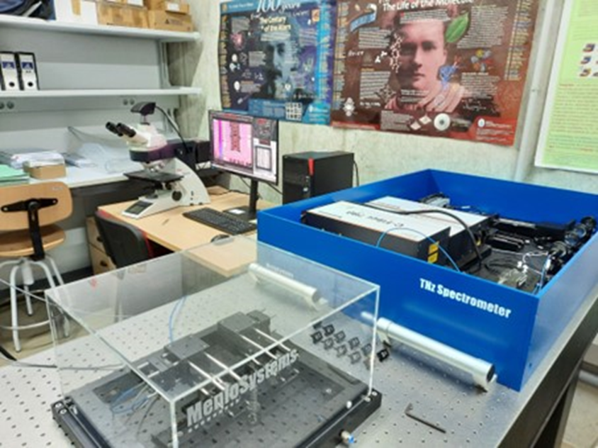
The second laser beam is directed towards the detector, where it also generates photocarriers. These carriers are accelerated by the electric field of the THz pulse, producing a very weak photocurrent that can be amplified and measured. This process is repeated many times, as the laser pulses have a repetition rate of around 100 MHz, so the value of the photocurrent that is recorded is actually an average value. Note that the signal obtained in this way is only a sample of a small fraction of the THz pulse, since this has a duration of picoseconds, while the laser pulse that triggers the detection at the receiving antenna has a much smaller duration, of the order of femtoseconds. In order to reconstruct the complete pulse, a variable and controllable time delay is introduced between the pulse that excites the THz generation and the one that triggers the detection at the receiver. This is achieved by means of an optical delay line, which introduces an optical path difference between the paths of the two beams. Usually, this delay line consists of a mirror moving on a mechanical or magnetic guide. By varying the position of the mirror, the difference in optical paths and thus the time delay is controlled, allowing the detector signal to be captured as a function of time (hence the name of this technique: time domain spectroscopy). The following figure shows a photograph of the THz spectroscopy equipment, Menlo Systems Tera K15, available at the Polytechnic University of Cartagena.
Once the pulse has been captured as a function of time, the application of the Fourier transform in amplitude and phase makes it possible to move from the time domain to the frequency domain, obtaining a spectrum in amplitude and another in phase (in this sense it is said to be a coherent detection scheme, unlike other spectroscopic techniques that allow only a spectrum in amplitude to be obtained). The frequency content of the signal obtained by this technique varies slightly from system to system, but can typically range from 0.1 THz to 4.5 THz. By obtaining both amplitude and phase information, it is possible to compare the spectrum obtained when a substance or material is within the optical path of propagation of the THz wave, and the same spectrum without that sample. From the comparison, the complex refractive index of the sample can be calculated, the real part being responsible for the time delay of one signal relative to the other (phase difference), while the imaginary part contains information concerning the absorption coefficient (attenuation of the signal).
III. THz APPLICATIONS IN INDUSTRY.
Spectroscopic fingerprinting in the THz region allows the detection of chemical substances and biomolecules, and also through materials that are opaque to the optical region of the spectrum (such as textiles, plastics, ceramics, paper or cardboard), a property that has begun to be used by the pharmaceutical, food, security and defence industries for the identification of substances such as drugs, explosives or weapons that may be concealed or hidden in their packaging. This has opened new doors to quality control and optimisation procedures in the manufacturing processes of these industries, allowing the detection of small variations in composition, defects, or other deviations in quality parameters, even when the products are already inside their packaging. Also, in the field of telecommunications and microelectronics, the THz range opens up new possibilities to meet the ever-increasing demand for bandwidth or to investigate ultra-fast processes in new semiconductors that are being explored for future faster and more efficient devices, such as graphene and other two-dimensional materials.
Some of these applications are described below:
(a) Plastics industry: non-destructive, non-contact analysis of many plastic materials is possible to find, for example, sub-surface fractures or delaminations, as well as the thickness of multi-layered materials and their dielectric properties.
(b) Protective coatings industry: enables non-destructive, non-contact quality control of all types of coatings and protective layers in conditions where other techniques would not work, such as on non-metallic substrates (e.g. on carbon fibre composites, widely used in the automotive and aerospace industry due to their lighter weight).
(c) Paper industry: A very important parameter in the paper industry is the determination of the moisture content of the paper in the production line. The THz makes it possible to measure not only the moisture content, but also the thickness and density of the paper rolls.
(d) Agriculture and food: The high sensitivity and contrast to humidity of THz imaging techniques allows in-situ measurements of water content in plant leaves. This makes it possible to assess plant stress under drought conditions and to optimise irrigation strategies, which is particularly relevant in arid and semi-desertified areas where water scarcity is a serious problem.
(e) Pharmaceutical industry: it is starting to use the THz technique in its quality control processes to check, for example, the composition of medicines and their dosage inside the packaging.
(f) Microelectronics and telecommunications: THz spectroscopy makes it possible to investigate the molecular dynamics of liquid crystals (used in various types of microelectronic, photonic and communications devices), as well as to determine various parameters of semiconductors, such as their conductivity and carrier density. The development of new materials such as graphene is benefiting from these techniques, as they make it possible to investigate phenomena that only occur in the THz frequency range (such as the propagation of surface electromagnetic waves called plasmons), as well as carrier dynamics on an ultra-fast time scale. In the field of telecommunications, THz allows the characterisation of new devices to be used for ultra-high bandwidth communications in this frequency range (antennas, filters, etc.).
(g) Security and Defence: of particular interest is the ability of THz techniques to detect hidden dangerous substances under conditions that no other technique could detect. This includes explosives as well as drugs and weapons. For example, THz scanners are already being tested in various airports around the world and applications in this sector will be increasing.
IV. BIOMEDICAL APPLICATIONS OF THz.
THz spectroscopy has been used in the investigation of various cancers, in particular skin, colon, and breast cancers. In these cases, the property exploited is the particular sensitivity of THz to the water content of the sample, as well as the non-ionising character of these electromagnetic waves. It is known that many cancers have a higher water concentration than normal tissues. This makes it possible to implement an imaging technique with THz waves in which healthy tissue can be accurately distinguished from cancerous tissue, both in ex vivo and in vivo samples. Instrumentation has even been developed to apply this technique in a surgical environment, helping the surgeon to accurately remove cancerous tissue without damaging healthy tissue. It is hoped that in the medium term this technique will reach a clinical implementation phase, becoming part of the biomedical technologies available in hospitals. Below, we briefly describe some of the trials that have already been conducted.
In the current surgical treatment of cancer there is an important need for techniques to guide the surgeon to remove cancerous tissue without damaging healthy tissue, leaving adequate margins in the removed tissue to ensure that the cancer has been completely removed and will not recur, while minimising the psychological and aesthetic effects of surgery.
A number of preoperative techniques are available to provide information on the location and size of the tumour. Mainly, these techniques are X-ray tomography, ultrasound imaging, and magnetic resonance imaging. However, at the time of surgery the application of these techniques is very limited, so there is a large component of uncertainty in deciding how much tissue to remove during surgery. The information provided by these techniques is only a rough guide to define the tumour margins.
Once in the operating theatre, there are several intraoperative alternatives to establish the tumour margins, but none of them are satisfactory at present. In some cases the tumour is palpable and can be located by the surgeon through his fingers, although this is a very subjective procedure. In cases where the tumour is not identifiable by touch, there are a variety of techniques ranging from a simple wire attached to the lesion preoperatively, guided by the preoperative instrumentation mentioned above, to techniques based on radioisotopes or ultrasound waves. In all cases the results obtained are very inefficient, with a high percentage of operations requiring one or more subsequent re-interventions due to tumour recurrence. The suffering caused in these cases, as well as the cost to the health system, makes it a priority to find a reliable technique to guide the surgeon during tumour removal.
THz technology has a number of properties that make it a viable technique for the assessment of tumour margins, and it has also been shown to be transferable to the operating table for use in real time during tumour removal. On the one hand, the wavelengths of THz radiation are longer than those of the visible or infrared spectrum, which means that an imaging technique that is not limited by light scattering processes in biological tissue can be implemented with it. At the same time, these wavelengths are safe for living organisms (they are non-ionising, unlike, for example, x-rays). Finally, they are highly sensitive to the water content of tissues, which makes them particularly suitable for the detection and visualisation of cancerous tissues and their discrimination with respect to healthy tissues (given their different water content). The studies performed so far demonstrate very good agreement between THz imaging of tumours and histopathological studies. The results show that THz signals can correctly identify the tissue type with a reliability of more than 92 %. Furthermore, an experimental probe has been designed for intraoperative use in the operating theatre in real time. In this instrument, the THz pulse is focused towards the probe tip by means of a special THz lens and beam steering prisms, which sweep across the active zone resulting in an image window of approximately 8 mm on a side. This image size is still small, but sufficient for initial studies and clinical applications, as it allows to visualise both the size of the tumour and a safety margin around the tumour to ensure its complete removal.
The physical processes or mechanisms that cause contrast in THz images of cancerous tissue are not yet fully understood. This requires further study of the relationship between the reflected pulses captured by the probe and the changes in the pathological characteristics of the tissue. Initial studies have measured the refractive index and absorption coefficient of tumour tissues on the one hand and healthy fatty and fibrous tissues on the other, finding significant differences that may explain the observed contrast. However, the field of medical imaging with THz technology is still in its infancy and much remains to be done to demonstrate its true potential before it is widely adopted by the medical community.
V. THZ FREQUENCY TELECOMMUNICATION DEVICES AT THE POLYTECHNIC UNIVERSITY OF CARTAGENA: FREQUENCY SELECTOR SURFACES (FSS)
At the Polytechnic University of Cartagena we have been working on the design, fabrication and characterisation of telecommunication devices at THz frequencies. Efforts have initially concentrated on Frequency Selector Surfaces (FSS), as described in the following sections, although other types of studies have also been carried out in the initial phase, such as the analysis of biological substances at THz frequencies.
V.1 Frequency Selector Surfaces (FSS)
A frequency selective surface (FSS or Frequency Selective Surface) is a periodic, planar structure of elements, usually metallic, on a dielectric substrate [1]. It acts as a selective barrier for electromagnetic waves propagating through it, manipulating the spectral content of the waves. As a result, some of the frequency components of the wave are blocked, while others pass through the structure. An FSS is therefore analogous to a circuit theory filter. In electromagnetic engineering it is also known as a spatial filter, by analogy with spatial filters in the field of optics.
The operating principle of traditional SSFs is based on the idea of resonant elements. When a plane wave is incident on a distribution of metallic elements, it excites electric currents in the metal. The amplitude of the currents generated depends on the degree of coupling between the wave and the structure. This coupling is maximum at the so-called fundamental frequency, at which the length of the elements is equal to lambda/2. Consequently, the elements are designed to resonate around the operating frequency. In turn, the generated currents act as sources of electromagnetic radiation, producing a scattered field. This scattered electromagnetic field is added to the incident field around the SSF, resulting in a total field that can be controlled by the proper design of the shape and distribution of the elements to obtain the required filter response. The frequency behavior of the HSS depends on the current distribution in the elements, and this in turn depends on the shape of the elements.
V.2. FSS at THz frequencies
Satellite communications systems have continuously evolved towards higher and higher frequency bands in order to take advantage of the greater bandwidth inherent in higher frequencies. From the low microwave bands (between 1 and 18 GHz) traditionally used, we moved to the first generation of Ka-band satellites (30/20 GHz), providing transmission speeds of 10 Gbps in the first generation and more than 100 Gbps in the second generation. However, the possibility of reaching higher bands such as Q and V (50/40 GHz) is limited by the higher atmospheric absorption at millimeter and submillimeter frequencies (from about 30 GHz), which requires the use of high transmission powers. Despite this, the exploration of this frequency range continues to be of priority interest, for example for its application in links between satellites, where propagation takes place in the absence of atmosphere, as well as for other applications of THz waves in fields already mentioned above, such as security and defense (remote sensing or remote detection services), biomedicine (biomolecule detection and biomedical imaging services), or quality control in numerous industries (from pharmaceuticals to food and agriculture, including plastics and paper). In all these applications, filters and other structures will be necessary for the correct manipulation of the signals, so the research and development of periodic structures in this frequency range offer interesting possibilities. Frequency-selective surfaces are a good example of a periodic structure. Comparing the propagation of electromagnetic waves in guided structures and in free space, we could say that FSS are the free space analog of electromagnetic gap structures (EBG) in guided propagation. Therefore, their study and understanding are indispensable for the development of future THz technology [2].
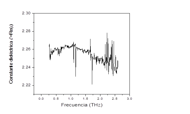
At the Polytechnic University of Cartagena we have worked on a frequency selector surface with a double bandpass in the range between 0.4 and 1.0 THz. It passes only two frequencies (two bands) in this range, reflecting all others. To achieve this, the FSS has two layers of metallic patterns on the top and bottom face of a dielectric substrate (254 micron thick Duroid 5880) that acts as a support. The first step in the design was precisely to characterize this dielectric substrate in the THz range, using a time domain THz spectrophotometer (Menlo TeraSync). With this instrument it was possible to determine the losses and permittivity of the substrate in the THz spectral range, and to use this data for the electromagnetic simulations in the design of the FSS. Previously, and in order to carry out these measurements, the metallic copper layer on each side of this dielectric was completely removed. The result is shown in Figs. 2 and 3, after applying the calculation procedure to extract the optical constants (or permittivity) from the transmission spectrum in amplitude and phase [3].
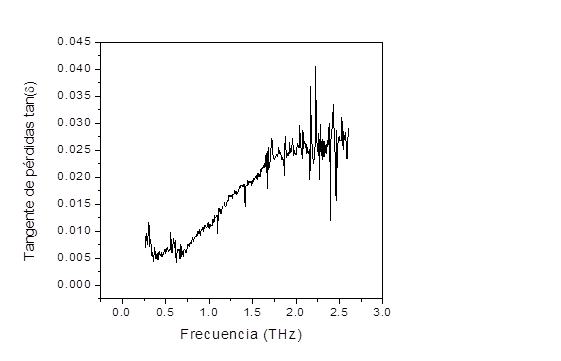
As can be seen in Fig. 2, the measurement result shows a reduced noise level up to the frequency of about 2.1 THz, with a couple of deviations at frequencies of 1.16 THz and 1.72 THz due to absorption by water vapor. The loss tangent in Fig. 3 shows how the losses are increasing with frequency, mainly due to an increase in absorption, until from about 2.1 THz the measurement becomes very noisy as a consequence of the low signal level detected. Therefore, we can consider that the measurement is reliable up to 2.1 THz.
In Fig. 3 we can see how the losses remain very low at frequencies below about 1 THz. In this range the loss tangent is less than 0.01. In view of this result we decided to concentrate the FSS design in this low loss range. The real part of the permittivity remains in this range at a value around 2.26, as shown in Fig. 2.
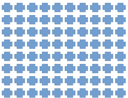
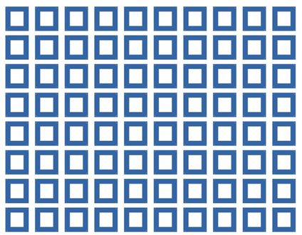
Once the characteristics of the substrate in the THz range are known, we move on to describe the design of the FSS. We have used the two copper metallized faces of the Duroid substrates in order to achieve a double bandgap structure. On each of these faces a different type of element was used for the periodic structure. On one side, on one of the faces we used an element belonging to the center-connected dipole group, namely two perpendicular crossed dipoles (Fig. 4). On the other side we used a closed-loop type element (squares in this case), as can be seen in Fig. 5.
The dimensions of the elements of each of the FSS faces were optimized by electromagnetic simulation (with HFSS) to achieve the desired passbands in the range between 0.4 and 1.0 THz. The influence of the motif dimensions on both the passband frequencies and the value of the return loss RL (dB), defined as the value of the reflection coefficient |S11| in the passband region, was analyzed. The objective was to reach a compromise to obtain optimum RL values in both bands. The optimum RL value is understood to be the lowest possible, since it is of interest that in the passband the reflected wave has the lowest possible intensity, while the transmitted wave is at its maximum. After a long optimization process, the following values for the motif dimensions were arrived at. For the crossed dipole face, the length of the cross arms (both horizontal and vertical) is 0.18 mm and the width of the arms is 57 microns. The spacing between crosses is 20 microns. For the face formed by closed squares, the outer side of the squares is 0.17 mm, while the inner side is 56 microns. The separation between squares is 30 microns.
V.3. FSS transmission spectrum
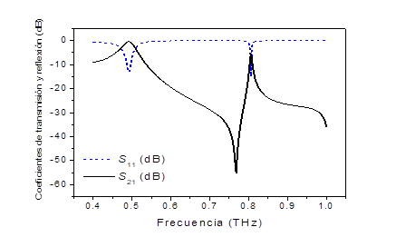
After completion of the optimization procedure for the dimensions of the FSS motifs, the result achieved for the transmission and reflection spectra is shown in Fig. 6 [4]. The two transmission frequencies observed are at 0.49 THz and 0.81 THz. The return loss in each of these bands are RL= -13 dB for the 0.49 THz frequency and RL= -14 dB for the 0.81 THz frequency. As previously mentioned, the lower this value the better the SSF characteristic in the corresponding band. The result achieved shows a good compromise between the two bands. The fabrication of the structure by microprocessing techniques and its subsequent characterization using the Menlo System Tera K15 THz spectroscopy system in transmission configuration show a good agreement between simulation and characterization of the structure.
The work with Frequency Selector Surfaces and THz spectroscopy at the Polytechnic University of Cartagena has been funded, among others, by the Research Project “Design and development of new high performance components for high frequency communications systems” (NEWCOSYS), PID2022-136590OB-C42.
References
[1] B. A. Munk, Frequency Selective Surfaces. Theory and Design, John Wiley & Sons, 2000
[2] P. Rodríguez-Ulibarri, S. A. Kuznetsov, y M. Beruete, “Wide angle terahertz sensing with a cross-dipole frequency selective surface”, Applied Physics Letters, vol. 108, pp. 111104, 2016.
[3] M. Scheller, C. Jansen, y M. Koch, “Analyzing sub-100 micrometer samples with transmission terahertz time domain spectroscopy”, Optics Communications, vol. 282, no. 7, pp. 1304-1306, 2009.
[4] J. Hinojosa, J. Aguilar-Pérez, y F. L. Martínez-Viviente, “Superficie selectora en frecuencia de doble banda de paso a frecuencias de THz”, XXXII Simposium Nacional de la Unión Científica Internacional de Radio, URSI 2017, Cartagena, 6-8 de septiembre de 2017.