
Antonio López Martín
Area Manager
Vice-Rectorate for Research of the Universidad Pública de Navarra
The detection of position, displacement, rotation or angular acceleration is critical in many of today’s control and measurement systems. Traditionally, such detection has been carried out by means of conventional potentiometers, consisting of a resistive strip along which a moving contact or cursor moves. The position of the cursor determines two resistances of variable value, the sum of which is the total resistance. These potentiometers are very cheap, but their useful life is reduced by the internal wear of the resistive strip due to the displacement of the cursor. This limitation prevents their use in many applications, so in recent years popular non-contact solutions have been developed that avoid this internal degradation. These new potentiometers are usually based on magnetic sensors, offering, in addition to a longer lifetime, other advantages such as: high accuracy, greater robustness against shocks, vibrations, humidity or contaminants, high operating temperature range and simple maintenance [1]. The main application sectors of these non-contact potentiometers are:
- Automotive: they are used in a multitude of systems in the transmission, engine, bodywork, etc.
- Industrial automation: used in robotics, CNC machines and position control in automated assembly lines, among others.
- Aerospace: used for example in flight control systems and landing aid systems.
- Medical devices: in surgery robots, prosthetics, medical imaging equipment, etc.
- Renewable energy: in precise positioning of solar panels and wind turbine rotors and blades.
The biggest challenges of these contactless technologies stem from the need to reduce size, cost and susceptibility to electromagnetic interference. To meet these challenges, highly integrated solutions using conventional CMOS technologies are desirable. The Public University of Navarra has developed together with the company PIHER a contactless potentiometer that addresses these challenges.
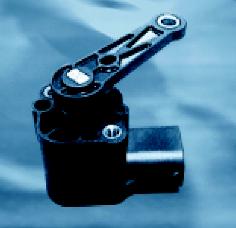
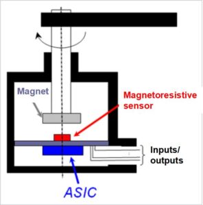
Figure 1: Non-contact potentiometer developed
(a) Photograph (b) Diagram
The device is shown in figure 1. At the end of the rotating shaft is a permanent magnet. Under the magnet is a two-layer PCB with a magnetic sensor on the top layer and an ASIC on the bottom layer. The magnetic sensor detects the direction of the magnetic field of the magnet and the ASIC processes the signal from the sensor, determining the angle. The interior is shielded and watertight to avoid electromagnetic interference and contaminants that can occur in hostile environments.
The magnetic sensor is a resistive Wheatstone bridge consisting of four giant magnetoresistors (GMR) [2]. The main advantage of this technology is its high sensitivity and the relative independence of the measurement with the magnetic field strength. The latter feature allows certain tolerances in the mechanical positions of the device components, making assembly cheaper. The size and cost of the internal PCB is also reduced by minimising the electronic components needed outside the ASIC, as this ASIC integrates almost all the necessary functionality.
Figure 2 shows the schematic of the developed ASIC. The ASIC biases the external sensor by supplying a constant current at the SENS0 pin. Due to the thermal dependence of the sensor voltage at this pin, the ASIC digitises this voltage and uses it for thermal compensation, without requiring an additional temperature sensor. The differential signal from the sensor is applied to a digitally programmable amplifier (PGA) and digitised in the ADC together with the temperature-dependent voltage. The digital part performs most of the signal processing tasks: offset, temperature and sensitivity compensation, linearisation, PWM output generation, etc. An integrated regulator allows the use of unregulated supply voltages, such as automotive battery voltage. Alternatively, a 5V voltage can be applied directly to the VDD pin. The ASIC also includes an EPROM for storing calibration and configuration parameters. An external resistor R is used to set the ASIC bias voltages and currents as well as the internal clock frequency. The ASIC has been designed to minimise area and cost, so analogue and digital blocks are reused as much as possible.
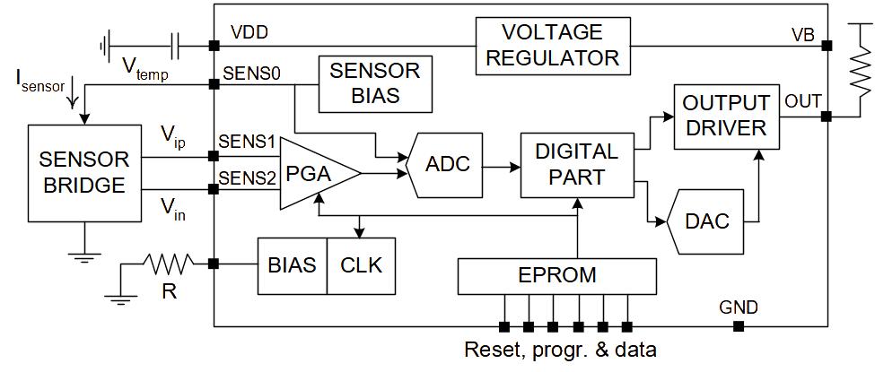
Figure 2. ASIC Floorplan
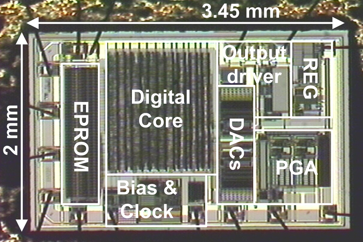
Figure 3: Photomicrograph of the ASIC
The 14-pin ASIC is manufactured in high-voltage CMOS technology suitable for automotive and harsh industrial environments. Figure 3 shows a micrograph. The total chip area is 6.9mm2. Figure 4 shows the duty cycle of the output PWM signal versus input angle after calibration. The ideal output is also shown. The duty cycle of the PWM signal was limited in the ASIC configuration to the extreme values of 5% and 95%. The maximum observed errors are +-0.5º over an angular range of more than 100º. These results demonstrate the accuracy achievable with this technology.
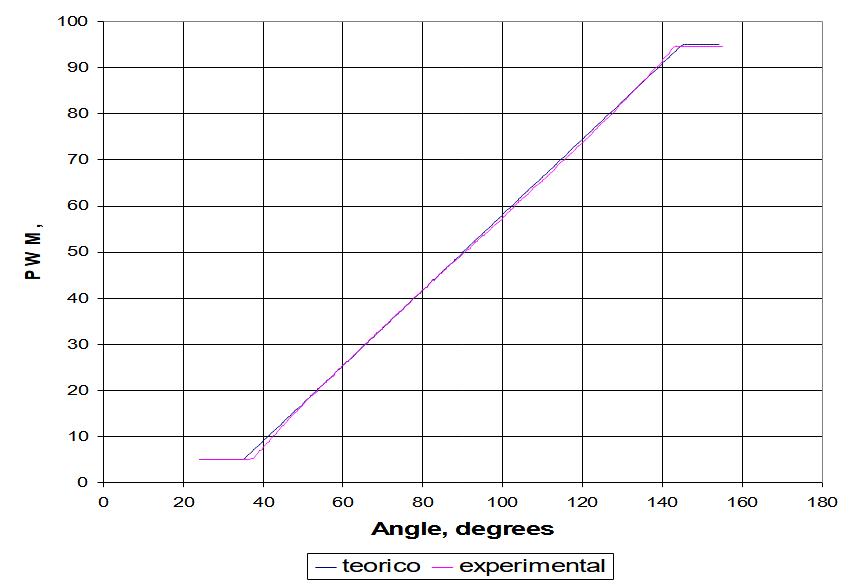
Figure 4: PWM output duty cycle as a function of input angle
[1] Kluvs Factory. The Power of Potentiometers in Automotive Applications: Trends and Future Developments. 9/10/2023
[2] H. Schewe and W. Schelter, “Industrial applications of magnetoresistive sensors,” Sens. Actuators A, vol. 59, pp. 165–167, 1997.